Frequently Asked Questions
Matrix™ FAQ
We have collected some common questions regarding our Matrix™ canisters. Please reach out if the FAQ does not answer your questions, or have a look at our videos in at the E-learning page.
Mobilisation/demobilisation
- Check that the subsea canister is properly mounted and connected to cathodic protection.
- Ensure that the end cap is properly mounted.
- Inspect and connect “FIBRE” connector.
- Verify that power source voltage, fuse and protective earth are within specifications.
- Make sure that the power source is deenergized before making the connection.
- Inspect and connect the “PWR” connector. Verify that the connector is fully mated and secure it with the locking ring.
- Inspect and connect cables to devices. Verify power rating and sufficient cross section of power conductors.
- Use dummy connectors on unused interfaces.
- Run through the pre-dive checks.
- Check that the subsea canister is properly mounted: orientation and fixation
- Check the environmental parameters, e.g. anodes, water temperatures, structure materials etc.
- Check and hand-tighten all connectors.
- Ensure that the air vent fitting is firmly capped! The cap should be hand-tighten, then tightened a bit more with a tool.
- Use dummy connectors on unused interfaces.
- Power on the system and check for any alarms.
- Set voltages, Ethernet speed and serial configuration as necessary.
- Set fuses to correct value according to equipment.
- Turn on external equipment and check that they are functioning properly, e.g. no ground fault or communication issues.
- If issues are found, check external equipment and cables for settings and/or damages. Use the troubleshooting guide,
The following should be performed after each dive:
- Rinse the outside of the subsea canister with fresh water.
- Visually check for damage, scratches, and pitting corrosion.
- Check all cables for wear or damage and hand-tighten all connectors.
It is important for the reliability of the system that cables and connectors are assembled and disassembled in a proper way.
Before assembly of cables please note the following points:
- Ensure that the cable integrity are intact and that no pins are damaged or corroded.
- Clean surface and pins with a suitable electro cleaner, type CRC 2.26 or equal.
- Dry off with clean cloth or compressed air.
- Grease the rubber section of the connector with a thin layer of Molycote 111 or equal.
- Assemble the connector and tighten by hand.
- All connectors that are not used must be plugged with depth rated dummy connectors.
Maintenance
After each dive, the subsea canister should be inspected for scratches in the anodised aluminium and pitting corrosion. Severe scratches in the anodised aluminium, especially near connectors, may lead to local pitting corrosion. If any scratches or pitting corrosion is found, a temporarily coat with Alodine Anodizing touch-up pen or similar should be used. Further use of the equipment without this temporarily coating is not recommended.
If pitting corrosion is found near seal surfaces, the unit must be inspected for seal integrity prior to diving. Contact Innova for service & support.
Their primary purpose is to prevent corrosion in other metal components, such as connectors and aluminium housing. As they are designed to be more reactive to corrosion than other metals, they will corrode and needs to be replaced when they are worn down.
Zinc anodes are replaced when sending the system in for service by Innova.
To prolong the life of the connectors, the following cleaning steps should be followed after each dive:
- Clean the plug and receptacle carefully with a non-metallic brush and soapy water. Suitable electro cleaners such as CRC 2-26 may also be used.
- Dry off excess water.
- Flood the connector with alcohol, then pour it out to allow the connector to air dry.
|
|
Caution: Compressed air may contain contaminants such as water, oil, and dirt, and is not recommended. Use alcohol only in well-ventilated areas. |

After the connector has been cleaned, perform an inspection of the connector:
- Inspect the connector pins for bent or deformed pins and corrosion.
- Inspect the rubber sealing surfaces for cuts, tears, and holes.
- The cable and rubber moulded plug must be free of cuts, tears, and rubber separations. Carefully inspect the rubber condition near the metal shell. Tears are common here, caused by using the connector in a bent position or using it as a handle.
- Finally, grease the rubber section of the connector with a thin layer of Molycote 111 or equivalent.
Even though all connectors are pressure rated to several thousand meters, installing dummy connectors is advised due to corrosion, there is small amount of current floating in the serial and ethernet part of the connectors although the power is switched off.
If the Matrix is disconnected from power, the salt water will lead to corrosion since the saltwater will act as an electrolyte between the different metals.
Settings recommendations
Check that the wiring is correct. There is one conductor that has to be connected inside.
Troubleshooting:
Ground fault
The Matrix features a ground fault detection system for the DC power delivery system. One of the onboard electronics boards applies a DC voltage between 0 V and PE, and measures the current flowing between them. The measured current is proportional to insulation – no current indicates a high/infinite insulation, and a high current indicates low insulation/ground fault.
All power output channels are galvanically isolated via 2-pole relays. This ensures that a ground fault on one power output channel will not affect other power output channels. There is still a small amount of current from the signal out on the connectors from Ethernet, serial and PPS channels.
C4, C5 and C6 are video connectors, which use a coax cable. The coax shield is connected to 0 VDC of the power output. If there is a bad connection on the camera, this will induce a ground fault to that power output.
- In the event of a ground fault, the following steps are recommended to locate the ground fault:
- Turn off all power outputs.
- Check “Status page” on the topside unit.
- If the ground fault value is infinite, proceed to the next step.
- If the ground fault is not infinite, e.g. 500 kΩ
- Turn on one power output, check ground fault value. If it is still infinite, go to the next step.
- Repeat step 3 until the ground fault found.
Serial
RS232 is a full-duplex, non-differential, standard for serial communication and data transmission. RS232 usually consists of three conductors – Rx, Tx and 0 V (ground/common). Tx from one device must be connected to the target device’s Rx port, and vice versa. 0 V must be connected to target 0 V.
RS485 is a half-duplex, differential, standard for serial communication and data transmission. RS485 usually consists of three conductors: RS48+ (B), RS485- (A) and 0 V (ground/common). In contrast to RS232, RS485+ should always be connected to target RS485+, and vice versa with RS485-. 0 V should always be connected to 0 V of the target device.
Full-duplex means that data can be transmitted and received simultaneously, allowing for two-way communication without having to wait for one device to stop sending before the other starts.
An analogy to this would be the telephone, both parties can talk and listen simultaneously.
Half-duplex means that data can be sent in both directions, but not simultaneously. In contrast to full-duplex, this means that one device must wait until the transmission is complete for it can start to send a transmission.
An analogy to this would be a radio/walkie-talkie; only one party can send traffic at any given time, the other party must wait until the first party is done with the transmission (talking).
Non-differential signal means that a signal is transmitted over one conductor with a common reference point, usually ground.
Differential signal means that a signal is transmitted over two conductors. The signal is represented by the voltage difference between the two conductors. This means that a common reference point such as ground is usually not needed (though it provides noise reduction, enhances signal integrity and other neat things).
The most common issues with serial communication are usually Tx/Rx faults, faulty cables and baud rate. The following steps may be used to troubleshoot serial communications issues:
- Ensure the 0 VDC (common/ground) is connected.
- Check the instruments manual that Tx/Rx is wired the correct way.
- Check the back on the topside unit. For each serial channel there are two LEDs, one for Tx (green light) and one for Rx (orange light). Use these lights to see if the channel is sending and receiving data properly.
- Is 0 VDC (common/ground) connected?
- Is +/- correct on both topside and subsea?
The serial channels on the Matrix are fully transparent, meaning that they do not affect the data being transmitted on the channels. This means that the system will support whatever baud rate, parity settings etc. that the devices need. The data is simply sent to/from the devices connect via serial channels, without any data handling or interference.
Ethernet
C9 and C3 are connected to a switch inside the Matrix canister. To communicate with Ethernet equipment connected to C9, you have to connect your topside control device to the C3 Ethernet port on the Topside unit.
The 4 channel Ethernet board connects the subsea Ethernet channels to the topside Ethernet
system. The communication speed on channel 1 to 2 is set to 1 Gbps and used for MBE's (C1 &
C2). Channel 3 is set to 1 Gbps and connected to a switch which provides 2 off 100 Mbps lines to the
Multi interface connector (C3), and one to C9. Channel 4 is not used.
Triggers
Signal Level output is 5 VDC. The trigger/PPS signal will mimic the signal sent in on the topside channel out to the subsea channel.
Signal input is 5-24 VDC, with 5 VDC being the default. To set this to a non-default value, please contact Matrix Support at matrixsupport@innova.no for help and instructions.
Fuses
The Matrix power controller boards have a feature for each power output channel called “Driver Fault Config”. This feature reads the fault condition from the semiconductor power switches, and turns off the power output channel if it reads any. The fault is activated if the semiconductor is too hot (power draw too high), or the output current is too low and/or pulsating (300 mA or lower).
If the device connected to a power output has a low power draw (less than 300 mA) or has a pulsating power draw, it might trip the fuse too early. Disabling the Driver Fault Config will help with this issue.
Fibre
The reason for this might be several reasons:
- If possible, check the system on deck with 15 dB attenuator. The readout on the software should be in the area 19-23 dB.
- Check the loss with an OTDR
Fibre-optic budget
Before any operation/dive with the multiplexer, it is advised to set up a fibre-optic budget for the job. A fibre-optic budget for a typical setup might look something like this:
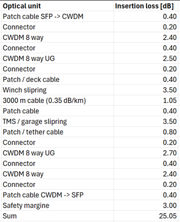
Doing so will let the operators know beforehand if the system can handle the setup, and if it can handle any unforeseen events.
Thermal
Temperature affects all electronic components, usually in lifetime degradation and/or temperature-induced failure.
The higher the temperature of the components, the lower the lifetime of the component is. Usually, most components can handle temperatures up to 70 °C, although many can handle even higher temperatures.
The Matrix has several different temperature sensors which measures the temperature inside the canister (and topside). The hottest component is almost always the SFPs, which will experience temperatures up to 70 °C (and higher in some instances). As the SFPs are rated to 70 °C, an alarm in the topside GUI will arise when the temperature on any SFP reach that value or above.
Note that the SFPs have a MTBF (Mean Time Before Failure) of 4 million hours at 70 °C, which means that 50 % of them are expected to still operate after 4 million hours at a constant temperature of 70 °C.
For every 10 degrees higher than rated temperature, the MTBF will be reduced by 50 %. So, at 80 °C the MTBF will be 2 million hours. Which means that you can operate the system at higher temperature, but warranty will be void as Innova can not ensure that the SFPs will handle the temperature.
If the canister internal temperature is high, it is recommended to do the following (if on deck/not in water):
- Keep away from direct sunlight
- Move to a cooler location (if possible)
- Continiously spray the canister with water
- Reduce/turn off power outputs
- Turn off the canister to let it cool down
Aluminium and titanium have different thermal properties which is important to heat development inside the canister, and how the canister should be operated.
Aluminium has a thermal conductivity of ~210 W/m*K, and titanium has a thermal conductivity of ~17 W/m*K.
In practice, this means that an aluminium canister is a lot more effective than titanium at transferring heat from the inside to the outside of the canister. The low thermal conductivity of the titanium means that it behaves more like a thermal insulator rather than a thermal conductor.
In environments where the temperature is low (such as 3000 m down in the ocean) this will not have an impact, but if the canisters are used in shallow waters during the summer this might cause internal temperature to rise in a titanium canister.
As the aluminium canister is anodised black to prevent corrosion, it will absorb more heat from the sun when operating in direct sunlight. Due to this, it is not recommended to operate the system in sunlight without adequate cooling.
Support
When contacting Matrix Support, it is appreciated if the following information is included in the email:
- Serial number of the system
- FW version of the topside unit (can be read from the status page)
- Troubleshooting steps attempted (power cycling, replacing cables, etc.)
- If relevant, which external equipment is used
Have more questions?
Get in touch with us
For more information or requests call us on
+47 51 96 17 00 or send an e-mail to service@innova.no.
Support
Schilling Support:
schilling.service@innova.no
Matrix Support:
matrixsupport@innova.no